According to Collins (2006), in the analysis of riveted joints and connections, it is generally assumed that the flexion and the traction on the rivets can be neglected, that the friction between the parts does not contribute to the transfer of force through the union, and that the stresses may be neglected. It is considered that the shear on the rivets is uniform and equally divided between the rivets. Thus, the critical points can be identified as: traction failure of the net cross section between two rivets, cross-section shear of the rivet, compressive support failure between the rivet and the plate, tearing of the plate at an edge, tearing of the plate across a row of rivets.
The failures considered for the rivet in question are caused by double shear stresses and crushing.
Double shear:
The fault identified by the team as the most critical was double shear, and it is for which the rivet design is being performed.
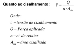
For shear rivets, the shear stress is given by the equation shown in Figure 1.
 |
| Fig 1. Shear stress equation. |
 |
| Fig 2. Crush stress equation. |
The failures considered for the sheet in question are those of axial traction, compression caused by the rivet and edge restraint caused by the rivet.
Axial Traction:
Considered by the team as the most critical fault for the plate, in the project in question, axial traction failure can be calculated by the following equation:
Where: 𝑏 = Plate width (mm), 𝐷ℎ = Hole diameter (mm), 𝐹𝑠 = Total shear load (N), 𝑁𝑟 = Number of rivets supporting load, 𝑡 = Plate thickness (mm), σ𝑡 = Tractive Stress (N / mm2);
Compression Caused by Rivet:
The compression caused by the rivet is in reality the compressive support failure, and the compressive support stress can be calculated from the equation:
Where: 𝐷𝑟 = Diameter of the rivet (mm), 𝐹𝑠 = Total shear load (N), 𝑁𝑟 = Number of rivets supporting the load, 𝑡 = Plate thickness (mm), σ𝑐 = Compressive support stress (N / mm2);
Tearing of the Plate at an Edge:
For the edge tear failure, the tearing tractive stress of the edge is demonstrated in the following equation:
Where: 𝑑𝑒 = Diameter of the hole to be riveted (mm), 𝐹𝑠 = Total shear load (N), 𝑁𝑟 = Number of rivets supporting the load, 𝑝 = Spacing between holes (mm), 𝑡 = Plate thickness (mm) , σ𝑒 = shear stress (N / mm2);


